
Electrolux Kelvinator AC Error Codes
Panasonic VRF AC Error Codes and Troubleshooting
Indoor unit is detecting error signal from remote controller (and system controller).
| Error Codes | Meaning |
|---|---|
| E01 | Error in receiving serial communication signal. |
| E02 | Error in transmitting serial communication signal. |
| E03 | Indoor unit is detecting error signal from remote controller. |
| E04 | Error in receiving serial communication signal. When turning on the power supply, the number of connected indoor units does not correspond to the number set. |
| E06 | Error of the outdoor unit in receiving serial communication signal from the indoor unit. |
| E08 | Indoor unit address setting is duplicated. |
| E09 | Remote controller address connector. |
| E12 | Starting auto address setting is prohibited. This alarm message shows that the auto address connector CN-A.ADD is shorted while other RC line is executing auto address operation. |
| E15 | Error in auto address setting. |
| E16 | Error in auto address setting. |
| E20 | No indoor unit is connected during auto address setting. |
| E24 | Main outdoor unit is detecting error signal from sub outdoor unit. |
| E25 | Error of outdoor unit address setting. |
| E26 | The number of connected main and sub outdoor units do not correspond to the number set at main outdoor unit PCB. |
| E29 | Error of sub outdoor unit in receiving serial communication signal from main outdoor unit. |
| E30 | Transmission from outdoor unit faulty. |
| E18 | Error of main indoor unit in receiving serial communication signal from sub indoor units. |
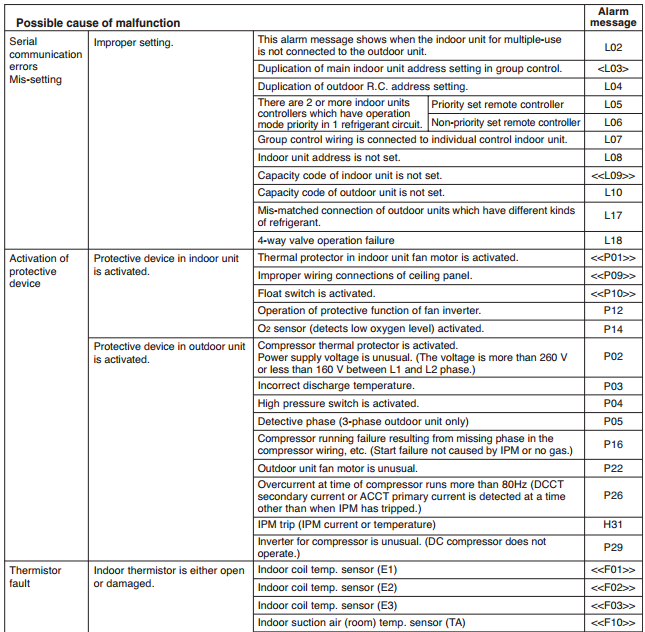
| L02 | This alarm message shows when the indoor unit for multiple-use is not connected to the outdoor unit. |
| L03 | Duplication of main indoor unit address setting in group control. |
| L04 | Duplication of outdoor R.C. address setting. |
| L05 | Priority set remote controller. |
| L06 | Non-priority set remote controller. |
| L07 | Group control wiring is connected to individual control indoor unit. |
| L08 | Indoor unit address is not set. |
| L09 | Capacity code of indoor unit is not set. |
| L10 | Capacity code of outdoor unit is not set. |
| L18 | 4-way valve operation failure. |
| P01 | Thermal protector in indoor unit fan motor is activated. |
| P09 | Improper wiring connections of ceiling panel. |
| P10 | Float switch is activated. |
| P12 | Operation of protective function of fan inverter |
| P03 | Incorrect discharge temperature. (Comp. No. 1) |
| P04 | The internal circuit of the high pressure switch is dead |
| P05 | Power supply circuit failure, missing-phase detection. |
| P13 | There is a trouble with the outdoor unit when the liquid valve and the gas valve are closed. |
| P14 | O2 sensor (detects low oxygen level) activated |
| P16 | Compressor running failure resulting from missing phase in the compressor wiring, etc. |
| P22 | Outdoor unit fan motor is unusual. |
| H31 | IPM trip (IPM current or temperature) |
| P29 | Missing-phase/reverse-phase in the compressor wiring, Compressor start-up failure |
| F01 | Indoor coil temp. sensor (E1) |
| F03 | Indoor coil temp. sensor (E3) |
| F10 | Indoor suction air (room) temp. sensor (TA) |
| F11 | Indoor discharge air temp. sensor (BL) |
| F04 | Compressor No. 1 discharge gas temp. sensor (TD) |
| F07 | Outdoor No. 1 coil liquid temp. sensor (C1) |
| F08 | Outdoor air temp. sensor (TO) |
| F12 | Compressor intake port temperature sensor (TS) |
| F16 | High pressure sensor failure |
| F29 | EEPROM on indoor unit PCB failure |
| F31 | EEPROM on the outdoor unit PCB is a failure. |
| H01 | Overcurrent of power supply current (CT) sensor |
| H02 | PAM failure |
| H03 | Power supply current (CT) sensor failure |
| C05 | Indoor or main outdoor unit is not operating correctly. Mis-wiring of control wiring between indoor unil, main outdoor unit and system controller. |
| C06 | Indoor or main outdoor unit is not operating correctly. Mis-wiring of control wiring between indoor unit, main outdoor unit and system controller. CN1 is not connected properly. |
| P30 | When using wireless remote controller or system controller, in order to check the alarm message in detail, connect wired remote controller to indoor unit temporarily. |


Troubleshooting
Trouble: The power LED on the outdoor unit control PCB does not turn ON.
Cause and correction: Check for any errors in the power wiring to the outdoor unit, and check for a missing phase.
Trouble: LED 1 and 2 on the outdoor unit control PCB do not turn OFF when the outdoor unit power is turned ON, and automatic address setting cannot be started.
Cause and correction: Check the “Alarm Displays” table and correct the problem.
Trouble: An alarm appears immediately when automatic address setting is started from the remote controller.
Cause and correction: Check the “Alarm Displays” table and correct the problem.
Trouble: Nothing happens when the operator attempts to start automatic address setting from the remote controller.
Cause and correction: Check that the remote controller wiring and the inter-unit control wiring are connected correctly. Check that the indoor unit power is ON.
Trouble: An alarm appears on the remote controller sometime from several seconds to several minutes after automatic address setting is started.
Cause and correction: Check the “Alarm Displays” table and correct the problem.
Trouble: LED 1 and 2 on the outdoor unit control PCB indicate that automatic address setting is in progress (the LEDs blink alternately) for several minutes after automatic address setting is started (the compressors may also start and stop several times), however LED 1 and 2 never indicate that automatic address setting is completed (turn OFF)


Comments
Post a Comment